

Data centers have evolved dramatically over the past two decades, and with the rise of AI, GPU clusters, and high-density computing, the humble raised access floor now plays a much larger role than most operators realize. From acting as a plenum for cool air to serving as a conduit for water pipes and cabling, the floor beneath the racks determines airflow efficiency, thermal balance, and even PUE performance. This guide walks through how airflow rate and floor height should be planned for both air-cooled and liquid-cooled data centers, based on international standards (TIA-942, ASHRAE TC9.9, Uptime Institute) and real-world project experience.
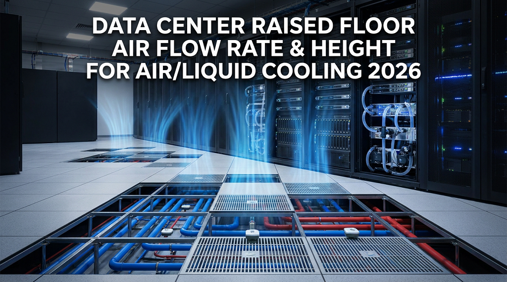
Before we look at the numbers, let’s start with the basics of what airflow through a raised floor actually means.
What is Air Flow for Raised Flooring in Data Center?
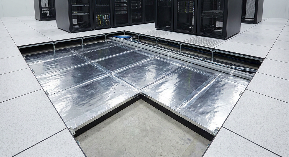
In a traditional air-cooled facility, the space beneath the raised floor is not just empty, it functions as a pressurized plenum that distributes cold air from CRAC/CRAH units to server racks through perforated tiles.
Two Core Functions of the Sub-Floor Plenum
- Air distribution: Chilled air fills the sealed cavity, builds static pressure, and flows upward through perforated tiles into the cold aisle. Servers pull in that cold air from the front and expel hot air out the rear.
- Cable routing: Power cables, PDU feeds, fiber, and network trunks are also placed under the floor, typically in a layered arrangement to avoid interference with airflow.
Perforation Rate Basics
Airflow rate is measured by the open area ratio of a perforated tile, calculated as effective vented area divided by total tile area (standard 600×600 mm). Common ranges:
- 17%–25% – low-density zones (storage, switch cabinets)
- 25%–40% – general server racks
- 40%–50% – high-density air-cooled zones with adjustable dampers
- Above 50% – rarely used, reduces load capacity and adds noise
Common perforation types include uniform round holes, long slots, micro-grids, and adjustable louvers. Round holes remain the most popular choice due to low noise, good dust resistance, and a flow coefficient of 0.65–0.75.
Now that we’ve covered airflow, let’s move on to the physical dimension that makes it all possible – floor height.
What is the Height of Raised Flooring in Data Center & Server Room?
The net clearance height (measured from the slab to the underside of the floor panel, excluding panel thickness) directly affects static pressure uniformity, cable capacity, and pipe routing space.
International Height Tiers (TIA-942 / ASHRAE)
- 300 mm (12 in) – Tier 1 edge rooms, cabling-only zones, ≤3 kW/rack
- 457–610 mm (18–24 in) – Tier 2 standard IDC, 3–15 kW/rack (global mainstream)
- 762–914 mm (30–36 in) – Tier 3 high-density air cooling, 15–20 kW/rack
- ≥762 mm (30 in) – Tier 4 fault-tolerant facilities, mandatory minimum
Why Height Matters
- Larger plenum volume = more uniform static pressure across the room
- Sufficient space allows proper strong/weak current cable stratification
- Reduces airflow resistance, which lowers fan power consumption
- Prevents dust turbulence caused by sub-floor air speeds exceeding 3 m/s
With these fundamentals in place, let’s look at how airflow rate and height should be matched for a conventional air-cooled data center.
Raised Floor Air Flow Rate & Height for Air Cooling Data Center
Traditional CRAC-based underfloor cooling remains the dominant architecture for existing IDCs and general-purpose enterprise rooms. Height determines pressure distribution, while perforation rate controls how that cold air is delivered to each rack.
Three Standard Height + Airflow Matching Models
🔹Model 1 – Shallow Plenum (300 mm, Tier 1)
- Rack load: ≤5 kW
- Recommended perforation: 20%–25%
- No cold aisle containment
- High-perforation tiles (40%+) forbidden, cause pressure loss at far ends
🔹Model 2 – Standard Plenum (457–610 mm, Tier 2 mainstream)
- Rack load: 3–15 kW
- Recommended perforation: 25%–35%
- Adjustable 35%–40% tiles for higher-load cabinets
- Pressure differential between near and far racks ≤10 Pa
- Best fit for 90% of existing and new general-purpose IDCs
🔹Model 3 – Deep Plenum (762 mm+, Tier 3/4 high density)
- Rack load: 15–20 kW
- Recommended perforation: 35%–45% with adjustable dampers
- Cold aisle containment required
- Zoned damper control matches dynamic load changes
❌Common Design Mistakes to Avoid
- Combining a 300 mm plenum with 40%+ perforated tiles → static pressure loss, far-end racks starve for air
- Using 17% low-perforation tiles across a 762 mm plenum → excess pressure, fans overwork, energy consumption climbs
- Mixing tiles with more than 15% perforation-rate variance in the same aisle → uneven flow and hot-cold air mixing
✅Practical Installation Rules
- Cable cross-section should not exceed 20% of the plenum’s total area
- Seal all floor seams and cutouts with brush strips to reduce leakage
- Perforated tiles go only in cold aisles; hot aisles and walkways use solid panels
- Install blanking panels in empty rack slots to stop internal air short-circuiting
Airflow-based cooling has limits, however. Once single-rack power exceeds about 20 kW, water-based systems take over, and that changes floor design entirely.
Raised Floor Air Flow Rate & Height for Liquid Cooling Data Center
Liquid cooling completely flips the logic of raised floor design. In a liquid-cooled facility, cold plates or immersion tanks handle 90% of the heat load, so the sub-floor no longer needs to move large volumes of air. Instead, it must accommodate water pipes, insulation, leak detection, and cable trays.
Height Tiers for Liquid Cooling
🔹500 mm (20 in) – Retrofit Minimum
- Applies only to existing air-cooled rooms converted to cold-plate liquid cooling
- Rack load: 20–30 kW
- Lower than 500 mm results in pipe crushing, insulation deformation, and blocked leak-detection lines
🔹610 mm (24 in) – New-Build Industry Standard
- Rack load: 20–40 kW
- Used by Google, AWS, and top Chinese cloud providers as the global benchmark
- Allows three-layer stratification: water pipes + leak detection at bottom, ventilation gap in middle, power/data cabling on top
- Real-world results: stable PUE at 1.18, zero condensation, easy valve maintenance
🔹762–914 mm (30–36 in) – Ultra-High-Density Clusters
- Rack load: 40–60 kW
- Suited for 10,000-GPU AI training halls with multi-loop CDU systems
- Extra space for thick insulation, large-diameter pipes, and redundant maintenance access
Immersion Cooling – No Rack-Area Raised Floor
- Rack zone uses a solid epoxy floor with 1% slope + drainage channels
- Walkways may keep a 250–300 mm low plenum for monitoring cabling only
- Full-height raised floors under immersion tanks are strictly forbidden per ASHRAE guidance
Air Flow Rate for Liquid Cooling Rooms
Perforated tiles in liquid-cooled rooms serve only three secondary purposes: auxiliary cooling of power supplies, disks, and memory; maintaining slight positive pressure against dust; and preventing condensation on cold water pipes.
- Standard cold-plate racks (20–40 kW) → 15%–20% perforation, cold aisle front only
- Ultra-high-density racks (40–60 kW) → 20% adjustable-damper tiles
- CDU and pipe manifold zones → 0% (solid panels only, to prevent condensation)
- Immersion tank zones → No vented tiles at all
✅Golden Rules for Liquid-Cooled Floor Design
- Never copy the high-perforation habits of air cooling—30%+ tiles will cause condensation, dripping, and false leak alarms
- Retrofit projects below 500 mm should abandon liquid cooling or first raise the floor
- Do not place perforated tiles directly over CDU pipes or valves
- Keep a 0.3%–0.5% floor slope with drainage points for water collection
❌Common Traps in Liquid-Cooled Deployments
- Copying air-cooled high perforation rates → widespread condensation, PUE rises
- Insufficient retrofit height (400 mm or less) → pipe damage, no leak visibility, doubled O&M cost
- Airflow tiles above CDU pipe zones → temperature swings and dew formation
- Full raised floor under immersion tanks → dielectric fluid spills cannot be contained
Once the airflow and height planning are set, the next step is choosing a raised floor system built to handle both traditional and modern high-density loads.
Recommended HUIYA Custom Raised Access Floor System
For projects that require serious load capacity, fire performance, and ESD control, from general IDCs to high-density AI compute halls, HUIYA Customized Heavy Duty Understructure Systems offer a proven solution.
Steel Encapsulated Calcium Sulphate Panels
- Dimensions: 600 × 600 × 30 mm
- Core: High-density calcium sulphate substrate (1,600 kg/m³)
- Encapsulation: Galvanized steel top (0.5 mm) and bottom (0.6 mm) plates
- Adhesive: DIABOND DC7000 (Japan) for durable panel-to-plate bonding
- Weight: 20 kg per piece
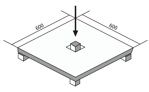
- Concentrated load: 4.5 kN with max 1 mm deflection
- Uniform load: 20 kN/m²
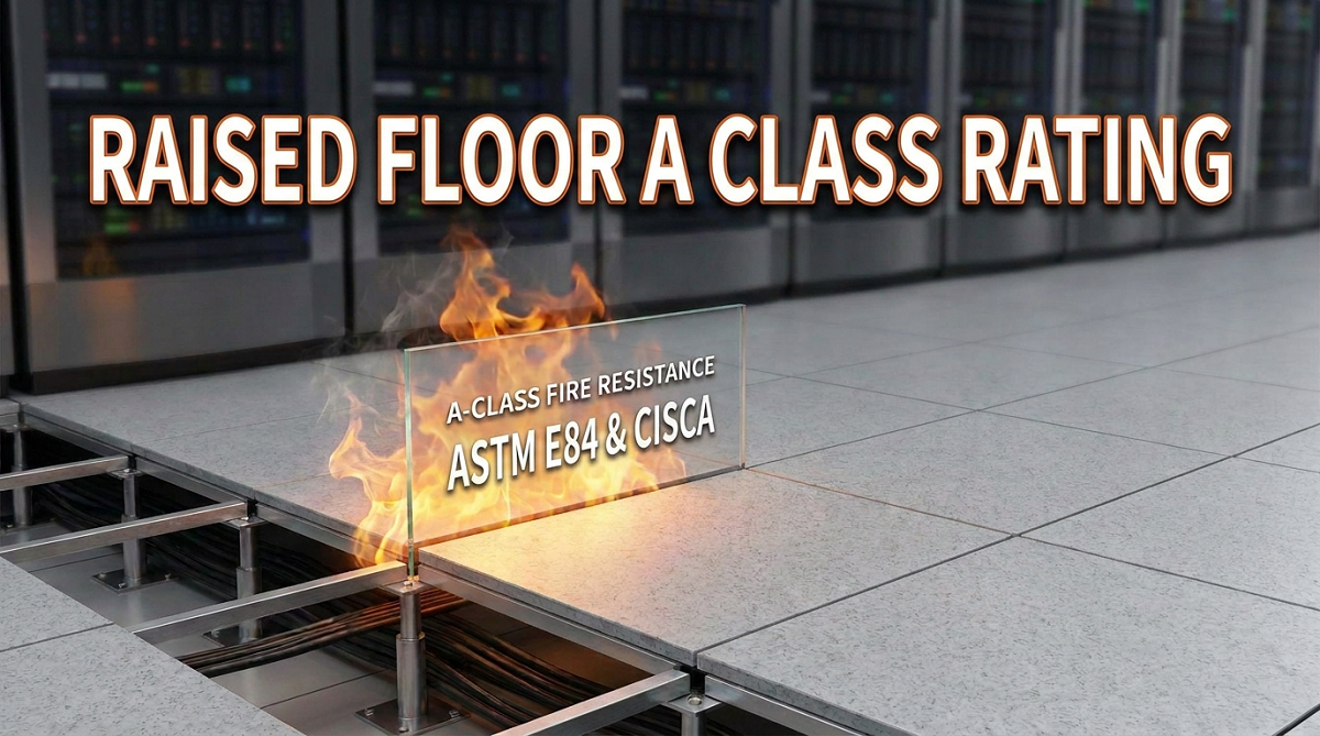
- Fire performance: 2-hour rating; passes EN 13501:2018 Bfl-s1
Heavy Duty Pedestal System
- Stem: Ø75 mm steel pipe, 3 mm wall thickness
- Base plate: 150 × 150 × 6 mm, up to Ø150 mm+ options
- Coating: Galvanized zinc 8 μm
- Vertical load capacity: 46 kN without collapse
- Height adjustment: Up to 100 mm with adjustable head types (flat, slot, or bolt-fixed)
- Supports raised floor heights up to 1,000 mm (custom versions up to 1,500 mm)
Heavy Duty Stringer System
- Dimensions: 21 × 32 × 540 mm
- Wall thickness: 1.5 mm
- Vertical load capacity: 20 kN
- Weight: 0.75 kg per piece
- Interlocking rolled-steel channel design distributes point loads and simplifies panel replacement
Finishes for Every Environment
- HPL / PVC / ceramic top finishes for offices and commercial rooms
- 3 mm anti-static, anti-slip ESD finish for server rooms
- Conductive PVC (EC: 1.0×10⁴–1.0×10⁶ Ω) and dissipative (SD: 1.0×10⁶–1.0×10⁹ Ω) options
- Human walking voltage <100 V (IEC 61340-4-5), static decay ≤2 seconds
Why HUIYA for Air and Liquid Cooling Rooms
- Height flexibility from 100 mm to 1,500 mm covers Tier 1 edge rooms through Tier 4 immersion walkways
- Heavy-duty pedestal + stringer combination supports the concentrated point loads typical of AI GPU racks
- Fire-rated calcium sulphate cores meet EU public-space safety codes, suitable for both office overlays and colocation halls
- Custom panel sizes and edge sealing (moisture and ESD) fit both air-plenum and liquid-piped applications
For customized quotations, panel samples, or project consultation, contact HUIYA at [email protected] or visit the Customized Heavy Duty Understructure Systems product page.
Related posts:
Huiya Real-Time News
Huiya Real-Time News is dedicated to providing you with the latest and most authoritative information on the raised flooring industry.
We provide 24/7 updates on industry policy interpretations, market trend analysis, company news.
MORE DOWNLOADS

GENERAL CATALOGUE
HUIYA INTRODUCTION

HUIYA GREEN LABEL
CAD/BIM FULL STEEL
APPLICATION SCENARIOS


