

On September 11, 2026, Changzhou Huiya Decoration Materials Co., Ltd. conducted an Ultimate Load Test on its 1500 LBS grade all-steel raised access floor panels. The test was carried out jointly by quality inspector Chen Wei and assistant Chai Lin, based on the breaking load evaluation method defined in CISCA 2007 Section 2, in combination with the safety factor requirements of EN 12825:2001, systematically verifying the ultimate load bearing capacity of Heavy Duty grade all-steel panels.
Following the August visit to the SGS third party testing institute in Changzhou and the September trip to Jinan to coordinate testing equipment and software solutions, Huiya has further implemented the related work into internal testing of specific samples, continuously refining the inspection procedures of its own in house laboratory across sample positioning, support layout, loading operations, and inspection records.
1. From External Method Learning to Internal Sample Testing
This test represents another practical implementation of Huiya’s recent “localization of the third party testing model” initiative. Prior to this test, the Huiya team had successfully completed two key preparatory tasks:
- 🔹On August 10, 2026, the Huiya team visited the SGS third party testing institute in Changzhou to systematically study the experimental procedures of CISCA 2007 and EN 12825, learn the testing methods for raised floor concentrated load, deflection, and permanent deformation, and observe on site the management of test devices, loading processes, environmental parameters, and raw records (see: Huiya Visits SGS Testing Institute to Study CISCA 2007 and EN 12825 Raised Floor Testing Methods).
- 🔹On September 3, 2026, the Huiya team traveled to Jinan, Shandong, to hold coordination discussions with the testing equipment manufacturer regarding the software reconstruction plan for the pressure testing machine, embedding the loading sequences, holding times, and evaluation thresholds of the two major international standards into the equipment control software in a modular fashion (see: Huiya Visits Jinan Equipment Supplier to Rebuild CISCA 2007 and EN 12825 Raised Floor Testing Software and Hardware Solutions).
This 1500 LBS all steel floor test represents the further practical application of the above work in internal quality inspection, marking the closure of the loop for both preparatory tasks, from “method learning” and “software and hardware alignment” to “routine sampling execution”. Through the testing of specific samples, Huiya aims to translate the method requirements from earlier study and technical exchange into executable and inspectable operational content, providing on site reference for future test procedure optimization and software function enhancement.
This process focuses not only on whether the equipment can apply the load, but also on how the specimen is installed, how the loading position is confirmed, how data is recorded, and how results are expressed differently under different testing bases.
2. Samples and Equipment: 1500 LBS Steel Floor Panels and Huiya’s In House Load Testing Machine
🔹Test Samples:
- Product type: All steel anti static raised access floor
- Specification: 600 mm × 600 mm mainstream panel size
- Rated load class: 1500 LBS (approximately 6,672 N), corresponding to Heavy Duty class in the CISCA 2007 grading
- Support method: Matched with heavy duty steel adjustable pedestals, simulating actual data center installation conditions
🔹Core Testing Equipment:
- Raised access anti static floor panel pressure testing machine (100 kN range, covering the breaking load range)
- High precision force sensor and lateral displacement gauge
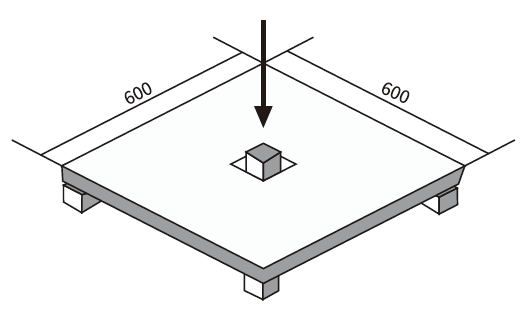
- 25.4 mm × 25.4 mm square loading indenter (compliant with the specification requirements of CISCA 2007 Section 2 breaking test)
- Bilingual Chinese and English test software with built in grading templates for GB/T 36340-2018, CISCA 2007, and EN 12825
Before testing, marking lines were drawn on the panel surface for positioning. Using the diagonal cross method, the panel center (Point A), edge midpoint (Point B), quarter diagonal position (Point C), and the 70 mm × 70 mm corner point from the corner (Point D) were marked. In accordance with CISCA 2007 Section 2 requirements, only one point is tested per panel (One point per panel), and 4 panels of the same batch were taken and loaded to failure separately.
3. Test Operations: From Sample Marking to Support Positioning
The main objective of this on site test was to determine the Ultimate Load of the raised access floor at the four key points (center A, edge midpoint B, quarter diagonal C, corner D) through continuous loading until structural failure occurs. The ultimate load is the maximum concentrated load that the panel can withstand before complete destruction. It is the highest performance indicator for evaluating the panel load bearing capacity, and is the sole original basis for subsequent calculation of the safety factor and determination of the Working Load and Design Load.
According to CISCA 2007 Section 2 requirements, the ultimate load is defined as: at a constant loading rate, the maximum force peak value in the panel force displacement curve is the Ultimate Load at that point.
Therefore, all operational procedures of this test were designed around “accurately, repeatably, and traceably capturing this peak value”. The test strictly followed seven steps: sample pre inspection, marking positioning, support system setup, specimen installation, indenter alignment, continuous loading to failure, and post failure verification. Only one point was tested per panel, and 4 samples of the same batch and same process were loaded to failure separately, obtaining 4 independent ultimate load readings.
Step 1: Sample Marking and Loading Point Positioning
Inspectors used rulers and marking tools to draw positioning lines on the front of each panel according to CISCA 2007 Section 2 requirements, providing reference for panel center identification and indenter alignment.
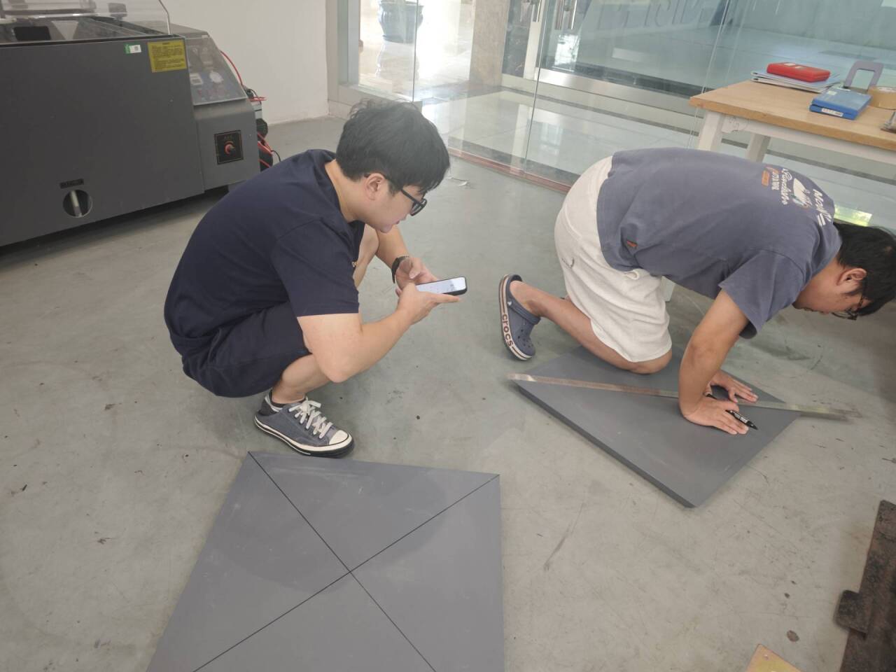
The marking references for the four points are as follows:
| No. | Loading Point | Marking Method |
|---|---|---|
| Point A | Panel center | Draw crossing lines along two diagonals, the intersection is the geometric center of the panel (300, 300) |
| Point B | Panel edge midpoint | Measure to the midpoint along one edge (0, 300 or 300, 0), 0 mm from the nearest edge |
| Point C | Quarter diagonal position | Measure 1/4 of the diagonal length from the panel center toward the corner along the main diagonal |
| Point D | 70 mm × 70 mm corner point | Retreat 70 mm inward from the panel corner along two adjacent edges, the intersection is Point D |
After marking, inspectors used a vernier caliper to verify the coordinate deviation of each point, controlling it within ±1 mm to ensure the 25.4 mm × 25.4 mm square indenter can be accurately positioned.
Step 2: Support System Setup (Simulating Actual Data Center Conditions)
To ensure that the ultimate load readings reflect the true load bearing capacity of the product in actual use, the support platform was constructed using the same heavy duty steel adjustable pedestal and stringer system as shipped:
- Pedestal configuration: 4 heavy duty steel adjustable pedestals, with 600 mm center distance, corresponding one to one with the four corner support points of the panel
- Stringer configuration: Cross shaped stringers installed on top of the pedestals (with acid and alkali resistant anti corrosion treatment), simulating actual installation conditions of class 100 cleanrooms and data center rooms
- Level calibration: A spirit level was used to level the pedestal platform, with corner height difference less than 0.2 mm
- Locking and fixing: All corner locking screws were tightened according to torque requirements to avoid additional displacement errors caused by support looseness during loading, which would affect peak reading
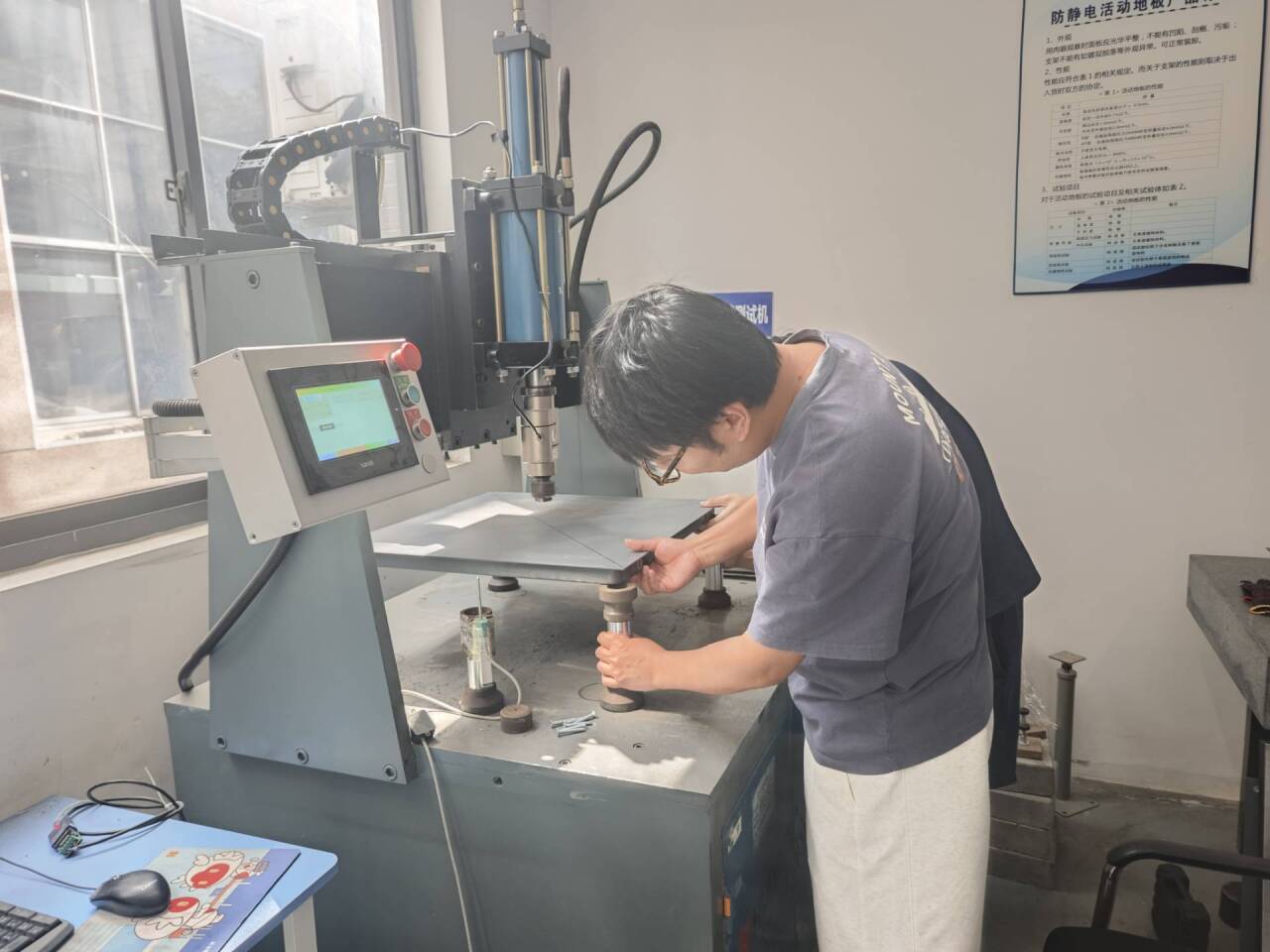
After setup, the total height of the support platform is 42 mm (panel thickness) plus pedestal adjustment height, consistent with the shipping standard configuration.
Step 3: Specimen Installation and Position Verification
The pre inspected and marked panel was gently placed on the pedestal platform, with the four corners accurately fitted into the pedestal tray positioning grooves:
- Position check: The panel is in full contact with the four pedestal trays, with no tilted corners or suspension
- Marking orientation: The marked side of the panel faces up, with the loading points (A / B / C / D) facing directly below the indenter
- Indenter centering pre check: After visual pre alignment, the software’s low speed descent mode (rate ≤ 1 mm/min) was used to lower the indenter to about 5 mm from the panel surface, and the coincidence of the marking cross point with the geometric center of the indenter was verified a second time
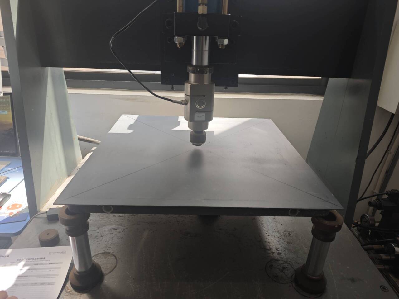
Excessive alignment deviation would lead to lower ultimate load readings. Therefore, this step requires the deviation to be controlled within ±1 mm.
Step 4: Indenter Alignment and Initial Parameter Setting
According to CISCA 2007 Section 2 requirements, the loading head uses a 25.4 mm × 25.4 mm (1 inch) square steel indenter with a flat bottom surface and no chamfered edges. The chief inspector completed the loading parameter settings in the control software:
- Test mode: Ultimate Load Test
- Loading method: Displacement control with synchronized force acquisition
- Loading rate: Constant (5 ± 1) mm/min, to avoid falsely high readings caused by impact effects
- Data sampling frequency: 100 Hz, recording the force displacement curve throughout
- Peak lock condition: When the force value drops significantly (≥ 20%) or the displacement increases sharply, the software automatically locks and records the peak force value as the Ultimate Load at that point
- Safety limit: Software protection is set to prevent the indenter from continuing to press down and damaging the equipment after failure
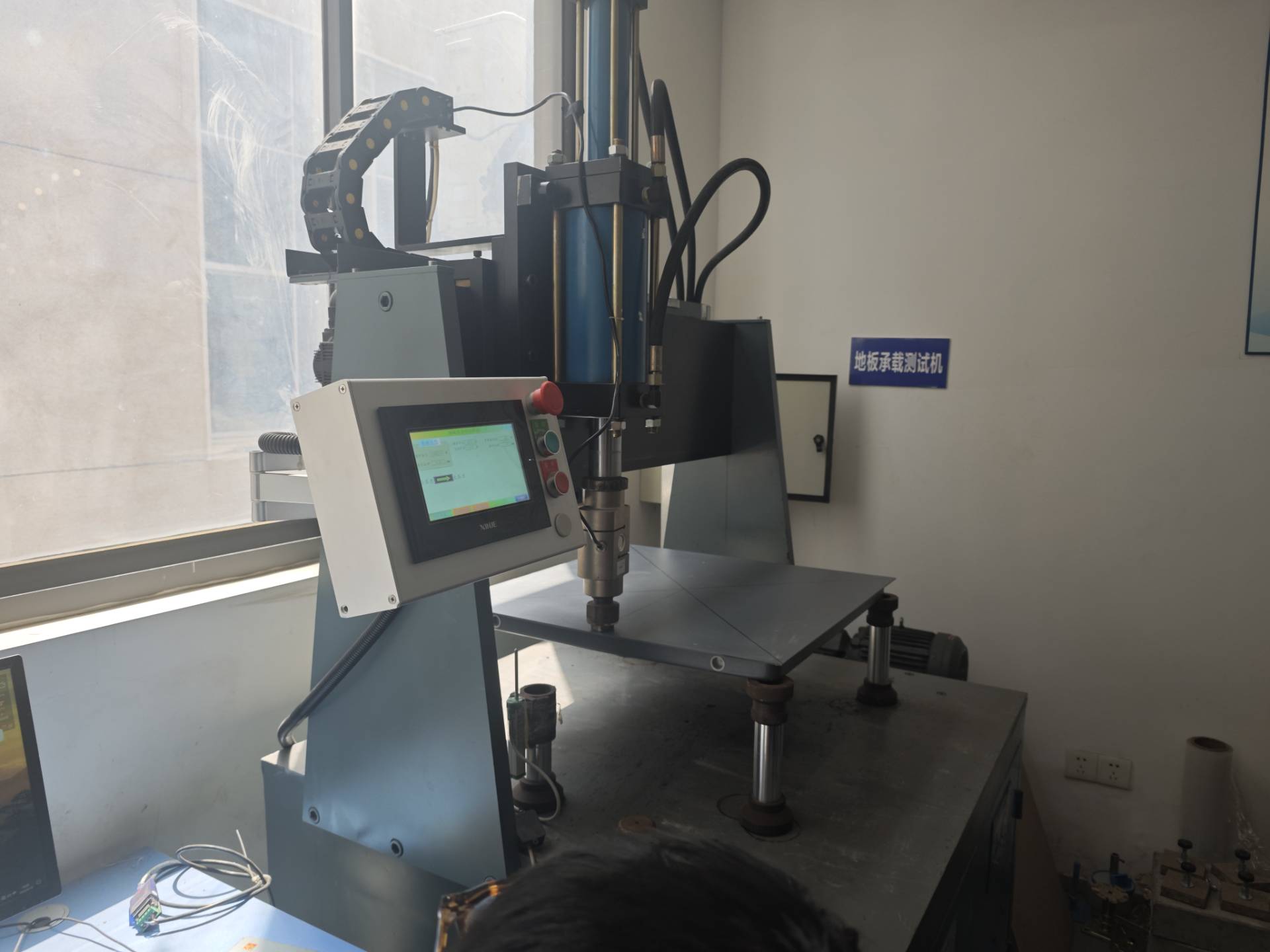
After parameter confirmation, the indenter was lowered to lightly contact the panel surface (preload ≤ 50 N), and the force and displacement readings were zeroed as the starting point for ultimate load measurement.
Step 5: Continuous Loading to Panel Failure and Ultimate Load Capture
The loading program was started, and the indenter continued to press down at a constant rate. The panel force displacement response went through three stages:
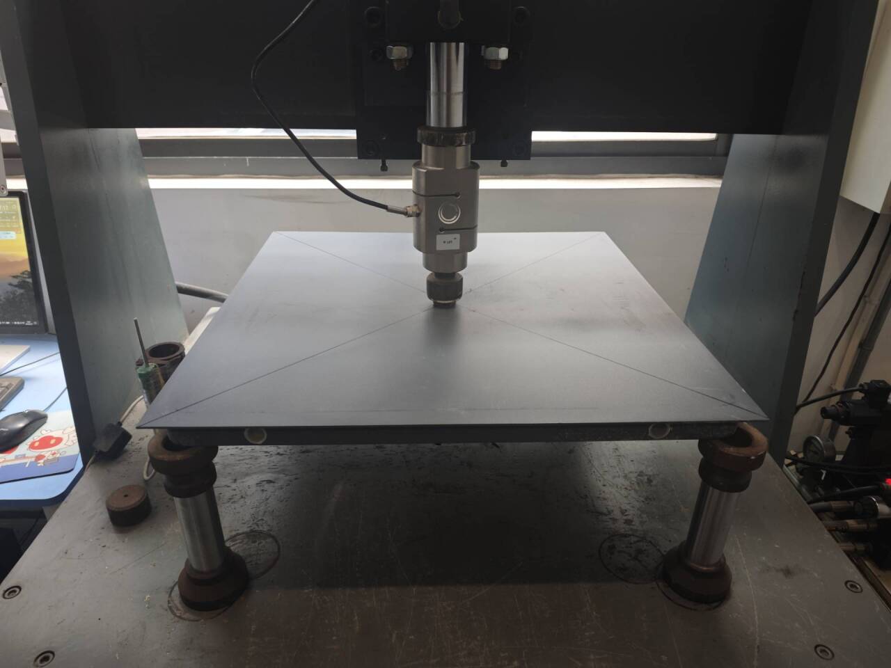
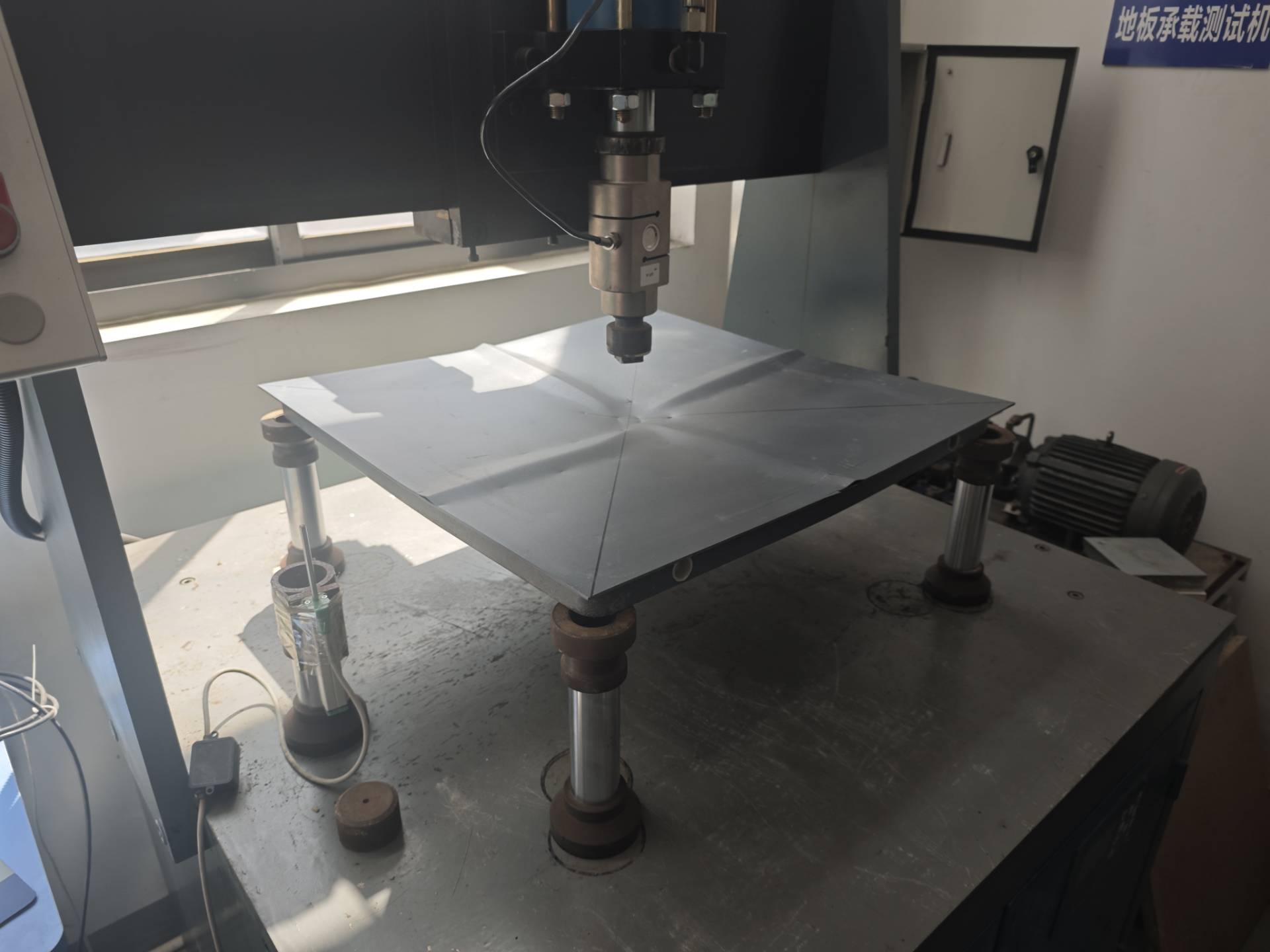
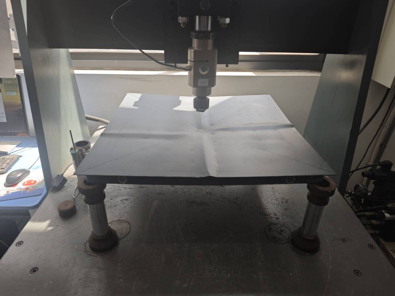
- Elastic stage: Force value rises linearly with displacement, with the slope reflecting the panel body stiffness
- Yield transition stage: The curve shows a nonlinear inflection point, and the panel enters plastic deformation
- Failure stage: After the force value reaches its peak, it drops sharply, accompanied by an obvious sound of structural failure
The highest reading automatically locked by the software at the moment of force value drop is the Ultimate Load at that point. The measured ultimate loads at the four points are as follows:
| Loading Point | Location Description | Measured Ultimate Load (N) |
|---|---|---|
| Point A | Panel center | 25,258 |
| Point B | Panel edge midpoint | 18,485 |
| Point C | Quarter diagonal | 19,051 |
| Point D | 70 mm × 70 mm corner point | 19,375 |
From the data, it can be seen intuitively that the panel center (Point A) has the strongest load bearing capacity, while the edge midpoint (Point B) is the weakest zone. This is a mechanical rule jointly determined by the 7×7 reinforcement rib structure on the back of the panel and the four corner support boundary conditions, and is also the reason why the lowest value at Point B should be used as the control point when determining the Working Load.
4. Implementing CISCA 2007 and EN 12825 Testing Requirements Separately
The 2007 edition of Recommended Test Procedures for Access Floors published by CISCA is the recommended testing procedure document for raised access floors, in which Section 1 specifies the Concentrated Load testing method and Section 2 specifies the Ultimate Load testing method. The two have different uses and different evaluation bases. EN 12825:2001 is the European standard for raised access floors, which explicitly requires that the breaking load be at least 2 times the working load (safety factor ≥ 2.0). In reports and news, the respective testing bases should be clearly stated to avoid general expressions.
In this internal test and subsequent process improvement, Huiya will focus on the following work:
✅ First, clarifying the testing task. This test adopts the CISCA 2007 Section 2 breaking test method, while referring to the EN 12825 safety factor requirements for result comparison.
✅ Second, refining operational records. Information such as sample installation, loading position, loading rate, and force and displacement readings at the moment of failure are included in the record organization.
✅ Third, distinguishing data from different stages. The elastic deformation, yield transition, and ultimate load at the moment of failure before failure are archived separately to avoid mixing.
✅ Fourth, advancing the connection between software and on site operations. Combined with the special nature of the breaking test (irreversible destruction), the loading parameter settings, peak capture logic, and failure determination fields are continuously improved.
It should be pointed out that this news records Huiya’s internal testing activities and does not constitute an SGS test report or third party certification statement. The connection between the earlier visit to SGS for study and this internal test is mainly reflected in the level of testing method learning and operational process improvement.
5. CISCA 2007 Ultimate Load Test: 1500 LBS Graded Loading and Deflection Recording
According to CISCA 2007 Section 2, the Ultimate Load Test method is: continuously apply pressure with a 25.4 mm × 25.4 mm square indenter at the specified panel point until the floor undergoes structural failure, and record the Ultimate Load at the moment of failure. Test points are arranged at 4 positions, with only one point tested per panel.
Test Point Diagram:
| Loading Point | Location Description (Test Location) |
|---|---|
| Point A | At the Centre of the Panel |
| Point B | At the Center of the Edge |
| Point C | A Quarter Along a Diagonal of the Panel |
| Point D | 70 mm × 70 mm from the Corner Along a Diagonal of the Panel |
Test Results:
| Test Location | Ultimate Load (N) |
|---|---|
| At the Centre of the Panel | 25,258 |
| At the Center of the Edge | 18,485 |
| A Quarter Along a Diagonal of the Panel | 19,051 |
| 70 mm × 70 mm from the Corner Along a Diagonal of the Panel | 19,375 |
The loading rate was controlled by the servo system throughout the process, the indenter accurately landed on the marking cross point, and the displacement gauge synchronously collected the panel deflection from the side. The software automatically recorded the complete force displacement curve, capturing the peak load and displacement at the moment of failure, forming a traceable raw data file.
From the on site photos and data curves, it can be seen that among the four points, the panel center has the highest breaking load (25,258 N), reflecting the strongest bending resistance of the panel body; the edge midpoint has the relatively lowest breaking load (18,485 N), which is consistent with the mechanical characteristics of the edge midpoint being less constrained by the pedestals and prone to early instability; the quarter position and corner point are between the two, reflecting the shear and warping resistance of the overlap area. The data distribution is consistent with the typical mechanical response of all steel raised floors.
6. EN 12825 Safety Factor Verification: Breaking Load vs. Working Load
EN 12825:2001 classifies raised access floors into Class 1 to Class 6 based on load bearing capacity, and requires that the Ultimate Load be at least 2 times the Working Load, i.e., the Safety Factor ≥ 2.0.
The rated working load of this sample is 1500 LBS ≈ 6,672 N. Dividing the measured ultimate load from the previous section by this working load yields the following safety factors at each point:
| Test Point | Ultimate Load (N) | Working Load (N) | Safety Factor | EN 12825 Requirement | Verdict |
|---|---|---|---|---|---|
| Panel center | 25,258 | 6,672 | 3.79 | ≥ 2.0 | ✔ Pass |
| Edge midpoint | 18,485 | 6,672 | 2.77 | ≥ 2.0 | ✔ Pass |
| Quarter diagonal | 19,051 | 6,672 | 2.86 | ≥ 2.0 | ✔ Pass |
| 70×70 mm corner point | 19,375 | 6,672 | 2.90 | ≥ 2.0 | ✔ Pass |
The safety factors at all four test points significantly exceed the EN 12825 lower limit of 2.0, with the safety factor at the most unfavorable point (edge midpoint) still reaching 2.77, indicating that this batch of 1500 LBS Heavy Duty all steel floor panels has sufficient structural redundancy in ultimate load bearing performance.
The loading indenter uses a 25.4 mm × 25.4 mm square specification, and the loading rate is kept stable to avoid impact effects interfering with the force reading at the moment of failure. All raw data (full force displacement curve, peak value at the moment of failure, loading rate, environmental parameters) are automatically archived by the reconstructed software system, with the field structure consistent with the presentation observed at the SGS laboratory earlier.
7. Making the “Third Party Perspective” a Norm Before Delivery
This breaking test was led by Chen Wei, quality inspector from Huiya’s QC department, responsible for sample positioning, loading parameter setting, software operation, and data interpretation at the moment of failure. Chai Lin, as the assistant, helped with sample handling, marking, pedestal installation, and post failure residue morphology verification. The two had clear on site division of labor and standardized processes, executing all operation nodes strictly according to the Raised Floor Finished Product Inspection Work Instruction.
Before the test, the two quality inspectors also re measured the surface flatness, edge straightness, and diagonal deviation of the unloaded samples of the same batch to check whether the samples in their initial state meet Huiya’s established factory inspection requirements for appearance and geometric dimensions (length and width 599.6 to 600 mm, height tolerance ±0.3 mm, initial edge flatness less than 0.5 mm, diagonal less than 0.75 mm), ensuring that the breaking test is conducted based on qualified blank panels.
- ✅For Huiya, this simultaneous 1500 LBS all steel floor CISCA 2007 Section 2 breaking test and EN 12825 safety factor verification has three levels of significance:
- ✅At the method level, it verifies that after the Jinan equipment manufacturer completed the software reconstruction, the pressure testing machine can now operate stably up to the breaking load range (maximum 25,258 N), fully capturing the peak and displacement data at the moment of failure, with the internal inspection method consistent with the operational procedures learned earlier at SGS.
- ✅At the product level, as a common raised floor product of Huiya for data centers, financial computer rooms, and class 100 cleanrooms, this batch of 1500 LBS all steel floor has safety factors ≥ 2.77 at all four key points, with a maximum of 3.79, leaving sufficient redundancy for long term customer use.
At the system level, it further extends the CISCA 2007 Section 2 breaking test and EN 12825 safety factor verification from an “external report of sampling for inspection” to a “routine self inspection item before delivery”, allowing each batch of finished products to receive a “near third party perspective” ultimate load bearing check up.
Huiya has long conducted multi system sampling inspections on finished products before delivery, including GB/T 36340-2018 (Chinese national standard), CISCA 2007 (American standard), BS EN 12825:2001 (European standard), KS F 4760 (Korean standard), and JIS A 1450:2005 (Japanese standard). This breaking test is a real record of the daily operation of this multi standard quality control system.
8. Continuously Improving Quality Management Through Specific Testing Work
From learning at third party laboratories, to technical coordination on equipment software, to this 1500 LBS all steel floor breaking test, Huiya is gradually implementing testing method improvements into internal quality inspection work.
Around the methods and procedures verified by this breaking test, the next stage of Huiya QC department will advance:
- 🔹Test coverage expansion: Fully incorporate CISCA 2007 Section 1 concentrated load (deflection and permanent deformation under working load) and Section 2 breaking load tests into routine sampling templates, simultaneously covering EN 12825 Class 1 to Class 6 grading.
- 🔹Sample category extension: Expand from all steel floor to steel concrete core floor, calcium sulphate core floor, wood core floor, and other categories, establishing respective ultimate load baseline data.
- 🔹Data traceability: All raw loading curves, breaking peak values, deflection readings, permanent deformation data, and environmental parameters are archived by batch, forming a long term traceable quality database.
- 🔹Personnel method comparison: Regularly arrange quality inspectors to visit SGS for method comparison tests, keeping the consistency deviation between internal inspection data and third party data within a reasonable range.
Raised access floors are not just decoration materials, but also the “second ground” that carries precision equipment and critical business. Huiya will continue to use international standards as the method baseline and stable quality data as the common language, working together with customers, design institutes, general contractors, and third party testing institutes to promote the Chinese raised access floor industry toward more standardized and traceable development.
Huiya Real-Time News
Huiya Real-Time News is dedicated to providing you with the latest and most authoritative information on the raised flooring industry.
We provide 24/7 updates on industry policy interpretations, market trend analysis, company news.

MORE DOWNLOADS

GENERAL CATALOGUE

HUIYA INTRODUCTION

HUIYA GREEN LABEL

CAD/BIM FULL STEEL
APPLICATION SCENARIOS


