

In recent years, the AI boom has triggered a quiet yet profound physical-layer revolution within the global data center industry. With the NVIDIA GB300 NVL72 rack pushing industry benchmarks to a power density of 135 kW, with peaks of up to 155 kW depending on configuration and workload, and Meta’s Prometheus cluster designed to utilize petabit-scale backend aggregation to interconnect tens of thousands of GPUs, internal thermal loads in data centers are surging. The traditional design paradigm relying on air cooling, underfloor air distribution, and underfloor cabling, is being overhauled or replaced. As operators deploy higher-density racks and extensive AI infrastructure, liquid cooling has emerged as an increasingly compelling thermal management solution. This raises the question: do the raised-floor systems, long the standard in traditional data centers, still offer advantages in a liquid-cooled environment? Furthermore, what alternative flooring solutions are compatible with liquid cooling, ensuring optimal operational efficiency for your data center? In this article, we examine the thermal density of AI-driven racks to explain why liquid cooling has become an inevitable evolution for data center HVAC systems. We also explore the ideal flooring solutions to various liquid-cooling technologies, including direct-to-chip (cold plate) cooling, rear-door heat exchangers, immersion cooling, and spray cooling.
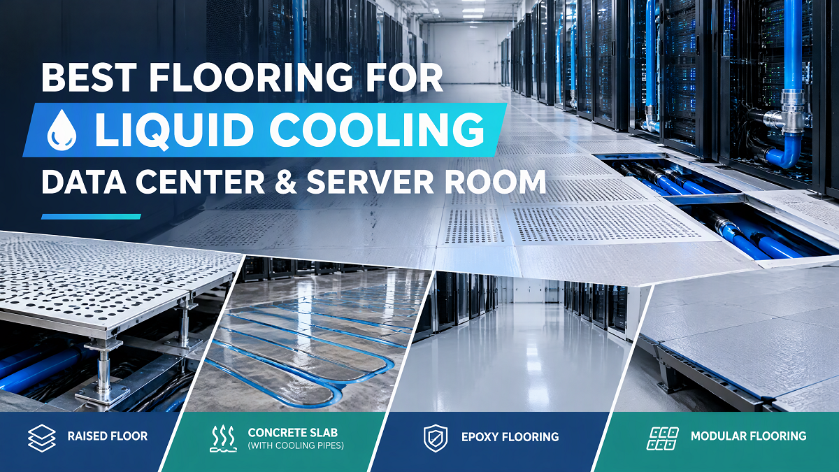
What Is a Liquid Cooling Data Center (Server Room)?
A liquid cooling data center uses a liquid medium, rather than air alone, to remove heat from IT equipment. Instead of relying entirely on fans and perforated tiles to carry heat away from processors, cold plates or dielectric fluid are brought directly to the heat source. The warmed liquid then travels through a Cooling Distribution Unit (CDU) that separates the facility water loop from the server coolant loop, and the heat finally leaves the building through cooling towers, dry coolers, or chillers.
Why this shift? Because every watt entering a server becomes heat that must leave the building. Traditional enterprise racks used to average 3 to 5 kW. Modern AI and GPU clusters routinely consume 50 to 100 kW per rack, with some new deployments approaching 200 kW. Air simply cannot transport that heat flux economically. Liquid can, because it carries far more energy per unit volume than air.
Why Data Center Flooring Changes: From Air Cooling to Liquid Cooling
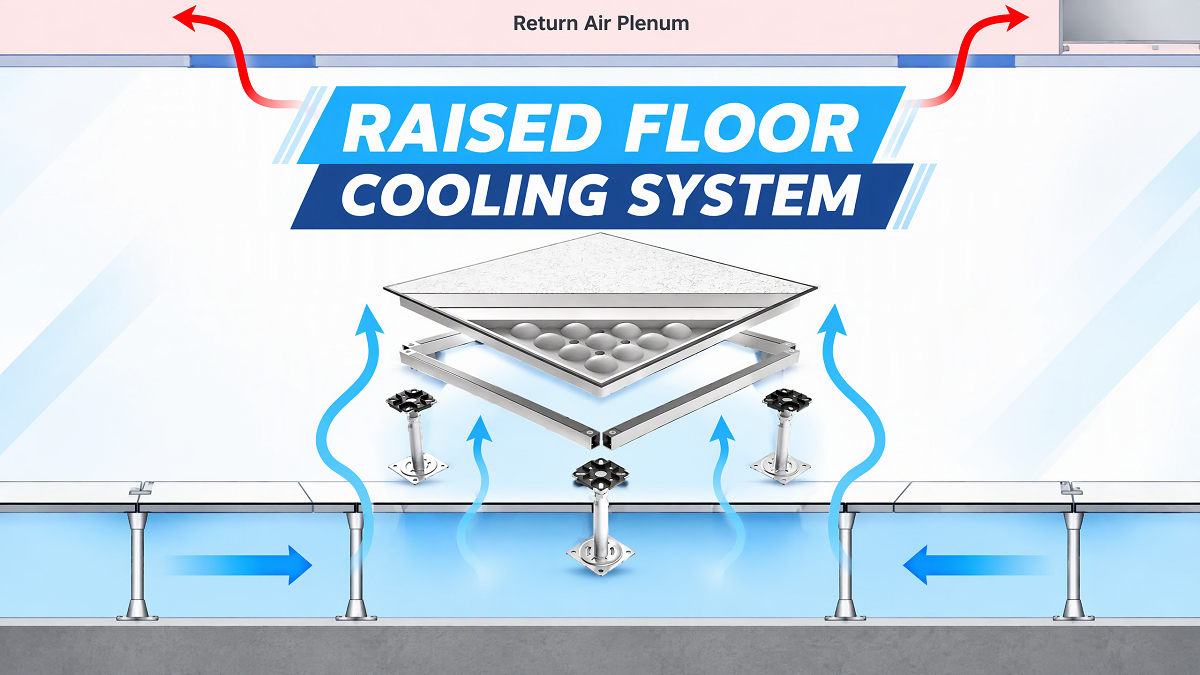
For decades, the raised access floor served one dominant job: act as a pressurized supply plenum for cold air. Cold air was pushed under the floor by CRAC or CRAH units, released through perforated tiles into the cold aisle, pulled through the servers, and returned as hot air to the cooling units. The floor was, in effect, a giant air duct.
Liquid cooling rewrites that brief. The underfloor void is now, in order of priority:
- A structural load path carrying heavy racks, CDUs, and filled tanks.
- A services void for secondary coolant piping, insulation, manifolds, and leak detection cable.
- A controlled drainage surface designed to catch and recover coolant when a joint fails.
- A secondary air pathway, if any air cooling remains at all.
Air-Cooled vs Liquid-Cooled Floor Requirements for Date Center & Server Room
| Parameter | Air-Cooled Hall | Liquid-Cooled Hall |
|---|---|---|
| Primary role of the void | Pressurized air plenum | Coolant piping, leak sensing, drip trays |
| Typical live load | 8–12 kN/m² (167–251 psf) | ≥12 kN/m² (cold plate); ≥20 kN/m² (vertical immersion) |
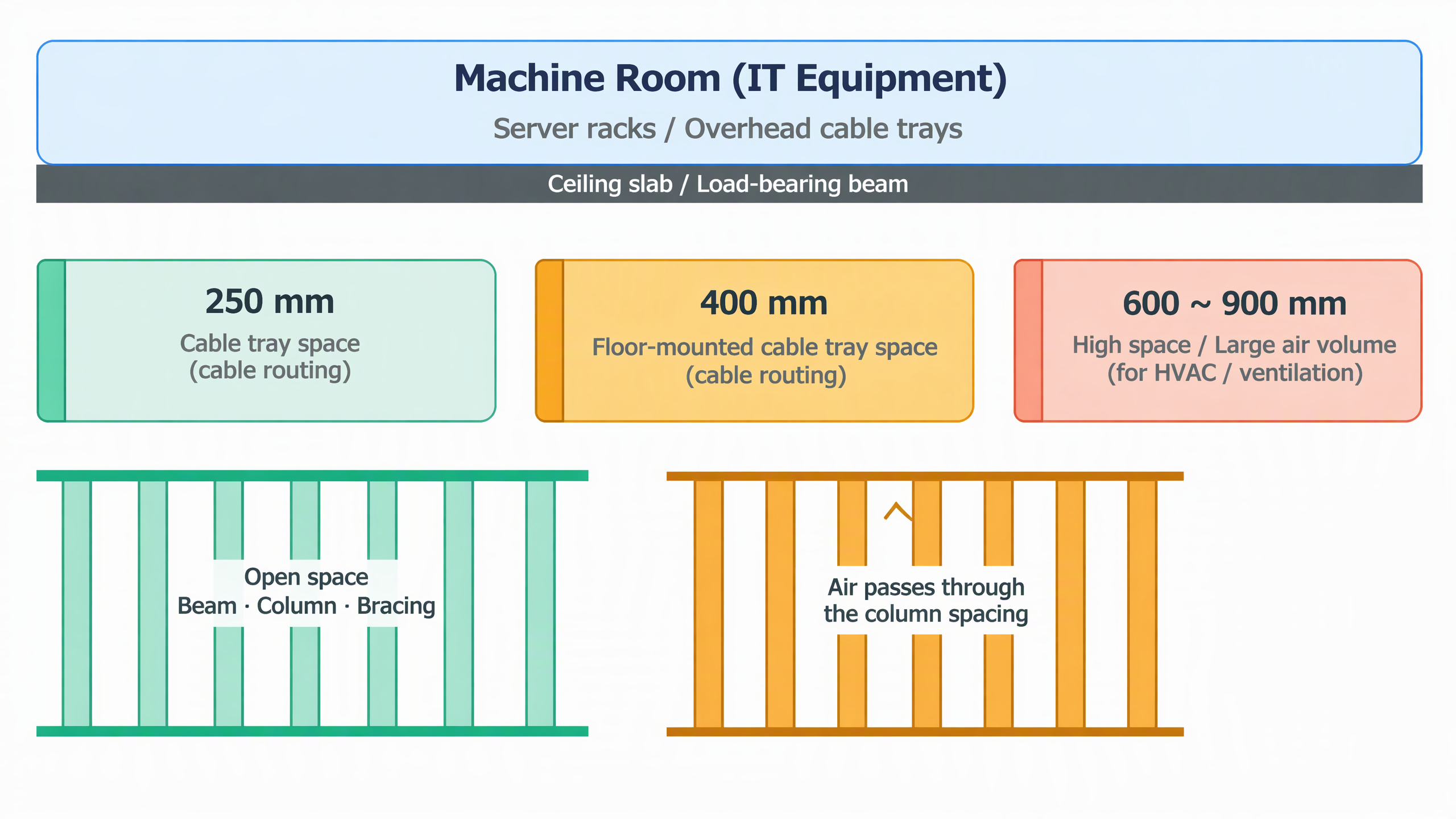
| Void depth | ≥250 mm (cable only); ≥500 mm (plenum) | ≥600 mm for secondary piping; ≥300 mm single-phase immersion |
| Perforated tile open area | 30–50% | 15–20% (cold plate); 0% (immersion zones) |
| Finish demands | ESD, wear-resistant, flat | Plus chemical resistance, non-absorbent, slip-resistant when wet |
| Dominant failure mode | Air short-circuit, hot spots | Leak-induced electrical fault, condensation, trapped fluid |
The core conflict is simple. Putting pressurized liquid lines into a plenum originally designed for cables and supply air means a single leak can migrate unseen through the void and reach the PDUs of several rack rows at once. That is the main reason hyperscale AI builds are moving to slab-on-grade with overhead busway and overhead coolant distribution.
Flooring Solutions for Different Liquid Cooling Systems in Data Centers
Liquid cooling transforms the floor from a “pressurized air-supply plenum” into a multifunctional assembly, serving as a load-bearing structure, a conduit for piping, and a surface designed to channel potential leaks. Not every liquid cooling system puts the same demands on the floor. Cold plate, immersion, spray, and rear-door heat exchangers all behave differently once a joint fails, a cabinet is loaded, or a maintenance trolley rolls across the aisle.Consequently, there is no “one-size-fits-all” flooring solution; the design must be tailored specifically to the chosen liquid-cooling architecture.
1. Single-Phase Cold Plate (Direct-to-Chip): Heavy-Duty ESD Raised Access Floor
Direct-to-chip (D2C) single-phase cold plate cooling is the most mature liquid cooling layout and the one most AI facilities are deploying today. Cold plates mount directly on CPUs and GPUs. A water or glycol/water mixture circulates through small channels inside the plate, absorbs the heat, and returns through secondary piping to a CDU that transfers the heat into the facility water loop. Because the loop is non-contact and runs at modest pressure, the raised access floor stays, but every one of its parameters needs to be recalculated.
Recommended floor system: heavy-duty antistatic raised access floor built from fully encapsulated steel panels, through-body ceramic, or heavy-duty die-cast aluminium, carried on a bolted-stringer understructure. For new ultra-high-density halls above the panel load envelope, evaluate slab-on-grade with overhead services instead.
Key design values:
- Clear void with secondary piping: ≥600 mm (24 in); 610 mm for 20–40 kW/rack, 762–914 mm for 40–60 kW/rack.
- Imposed slab load: ≥12 kN/m² (251 psf), per T/DZJN 524-2026 §8.2c.
- Panel working concentrated load: ≥6.67 kN (1,500 lbf); use the 11 kN (2,500 lbf) class for ultra-dense zones.
- Perforated tile open area: 15–20%, cold aisle only. Solid panels over CDUs, manifolds, and valve groups.
- Fall and drainage: 0.3–0.5% toward collection points, with drain valves on secondary mains.
Four piping rules worth memorising:
- Route secondary coolant piping beneath the raised floor, but keep mains directly above or below racks out of the design. Run power, telecom, and network mains above the racks. Where both must share the void, provide ≥600 mm clear height and separate liquid lines and power/data into front and rear aisle zones.
- Insulate all coolant piping. Design primary and secondary distribution as dual-path or ring mains with sectional isolation valves.
- Prefabricate pipe spools and pressure-test them after installation.
- Place leak detection at every joint, along pipe runs, and at rack bases.
Condensation control. The CDU must hold the TCS supply temperature above room dew point with a defined margin. Never place perforated tiles directly over coolant pipes, valves, or CDUs. Doing so produces condensation, drip, and false leak alarms.
CDU placement clearances. Allow ≥1 m on the service side, ≥1.2 m above racks for server lift-out, and ≥1.5 m for equipment transport aisles.
2. Two-Phase and Pumped Two-Phase Cold Plate: Chemical-Resistant Floor With Sealed Piping
Two-phase cold plate cooling uses the same geometry as single-phase, but the working fluid is a low-boiling-point dielectric that changes phase inside the cold plate itself. That shift adds a pressure boundary, vapour-side concerns, and tighter containment requirements, which in turn change what the floor has to do.
Recommended floor system: the single-phase cold plate build-up remains the starting point, but the finish moves toward chemical-resistant coatings in piping zones, and perforated tiles are removed from any path above refrigerant lines.
Additional design requirements over single-phase:
- Fluid recovery capacity sized for a pressure-boundary failure.
- Vapour detection and emergency ventilation sized for the specific fluid.
- A fire strategy based on the fluid’s safety data sheet, not on the single-phase cold plate template.
- Design pressure, wetted-material compatibility, and recovery routing agreed with the fluid supplier.
- No perforated tiles above refrigerant lines, under any circumstances.
3. Single-Phase Immersion, Horizontal Tanks: Chemical-Resistant Cast Floor With Perimeter Containment
Horizontal single-phase immersion submerges full servers in a dielectric fluid such as hydrocarbon oil, silicone oil, or a high-boiling-point fluorinated liquid inside a horizontal tank. The fluid is pumped through a heat exchanger and returned. A filled tank commonly exceeds 985 kg and can weigh several tonnes, and a spilled dielectric cannot be recovered or easily observed if it falls into an underfloor void. Both reasons point to the same conclusion: in the tank zone, drop the raised floor entirely.
Recommended floor system: cast-in-place chemical-resistant epoxy or polyurethane floor directly on the structural slab, with perimeter containment. Industry guidance is blunt here: never install a full raised floor beneath immersion tanks.
Recommended build-up in the tank zone:
- Structural slab, treated for dust and damp.
- Impermeable waterproofing layer.
- Seamless chemical-resistant epoxy or polyurethane coating, 3 to 5 mm, with anti-slip aggregate broadcast into the surface.
- Approximately 1% fall toward collection channels.
- Perimeter stainless steel or FRP channels, sump pits, and dedicated coolant-recovery drains.
- Surface resistance 10⁶ to 10⁹ Ω, with a copper-foil equipotential grid bonded to the building earth.
Verify the coating’s immersion compatibility with the actual fluid used (fluorinated liquid, silicone oil, hydrocarbon oil). Request immersion test data and the SDS from the coating supplier. Walkways and cable zones may retain a shallow 250 to 300 mm raised floor for monitoring and low-voltage cabling only, with no perforated tiles.
Load guidance: ≥12 kN/m² for horizontal layouts per Chinese practice. Project calculations frequently fall in the 1.5 to 2 t/m² range. Distinguish equivalent uniformly distributed live load from local bearing pressure at tank feet, which often governs.
Code references: T/CIE Design Specification for Single-Phase Immersion Liquid Cooling Data Centers §5.1.4 requires leakage bunds or trenches to collect coolant. §10.2.3 requires retaining bunds, leak detection, and coolant routing via dedicated drains to a recovery system. Discharge to drains or outdoors is prohibited.
4. Single-Phase Immersion, Vertical Cabinets: Slab-on-Grade With Shallow Raised Floor in Aisles
Vertical single-phase immersion packages the same technology into rack-style enclosures that sit upright. Each loaded cabinet concentrates significant weight on a small footprint, so the floor logic is simple: the cabinet goes on the slab, and access flooring is confined to walkways and cable routes.
Recommended floor system: slab-on-grade in the cabinet zone, with cabinets anchored to independent support frames that transfer load directly to the structural slab. Shallow raised access floor is used only in walkway and cable zones, with heavy-duty ceramic or all-steel panels in traffic areas.
Key design values:
- Slab live load: ≥20 kN/m² (418 psf / 2,039 kg/m²) for new vertical immersion halls.
- Rolling load check for inspection trolleys and server lifts in walkway panels.
- The access floor carries personnel and trolleys only; cabinet weight bypasses the floor system through independent frames.
Retrofit guidance. Chinese practice allows reduction factors of 0.8 for secondary beams and 0.75 for primary beams and vertical members, but requires a full assessment including transport loads, operating vibration, and a seismic appraisal to GB 50023. T/ZSA 216-2023 notes that unused halls can be strengthened with steel-beam framing or bonded FRP, with bonded steel plates preferred for secondary and frame beams. Bonded carbon-fibre strengthening should not be used in occupied halls.
5. Two-Phase (Phase-Change) Immersion: Impermeable Cast Floor Integrated With a Services Plinth
Two-phase immersion takes the submerged-server concept one step further. The dielectric fluid boils at the component surface, rises as vapour, and condenses on an overhead heat exchanger before falling back into the tank. The system is sealed and may be slightly pressurised, which introduces vapour loss, fire, and recovery concerns on top of everything demanded by single-phase immersion. The floor becomes part of the safety system.
Recommended floor system: impermeable cast floor plus an engineered services plinth directly beneath cabinets and cooling enclosures, built to handle fluid recovery, vapour management, and a fluid-specific fire strategy.
Additional design requirements over single-phase immersion:
- Services plinth higher than 0.6 m beneath cabinets, carrying primary-loop piping and power/data cabling.
- Clear height under beams preferably greater than 3 m.
- Water overflow, seepage, and splash protection designed at building-planning stage.
- Emergency ventilation exceeding 5 air changes per hour, with the exhaust outlet lower edge less than 0.3 m above the floor.
- Vapour concentration monitoring, including potential decomposition products.
- Effective storage tank capacity greater than 10% of total system volume; verify floor load capacity along mobile-fill-equipment routes.
- Fire strategy based on the specific fluid’s closed-cup flash point, auto-ignition temperature, and full-scale test data. Do not reuse the cold-plate fire package.
6. Spray Direct-Contact Cooling: Antistatic Floor Coating With Bunds and Drainage Trenches
Spray cooling sits between cold plate and immersion. A dielectric fluid is sprayed through a perforated plate directly onto heat-generating components and collected by gravity in a reservoir at the rack base. The rack itself incorporates the primary collection point, but spray drift, pipe leaks, and reservoir overflow all still have to be handled by the room floor. The relevant Chinese standard spells the finish out directly.
Recommended floor system: antistatic floor coating on the structural slab, with leakage bunds or drainage trenches to collect coolant.
Key design values and code references:
- T/CIE Design Specification for Spray Direct Liquid Cooling §5.1.6: the data hall floor “should use anti-static floor coating, with leakage bunds or trenches to collect coolant”.
- §5.1.4: keep power distribution cabinets away from water pipes; provide overflow and leak protection with water alarms.
- §5.2.1: live load ≥12 kN/m² in the data hall and ≥16 kN/m² in battery rooms.
- Sections 10 and 11: retaining bunds, leak detection, and dedicated drains beneath cabinets and coolant piping.
- Where a raised floor is used, provide ≥0.6 m void and ≥3.0 m clear height under beams. Underfloor piping is preferred.
7. Rear-Door Heat Exchangers (RDHx) and Hybrid Air/Liquid Retrofits: Retain the Raised Floor, Strengthen Locally
Rear-door heat exchangers mount a liquid-cooled coil directly on the back of each rack. As hot air exits the server, it passes through the coil and gives up its heat to a chilled-water loop before re-entering the room. In many hybrid halls, RDHx is paired with cold plates on the silicon and air cooling for the rest of the server, which means coolant piping and perforated tiles share the same floor plan. The least disruptive answer is to keep the existing raised floor and strengthen it locally.
Recommended floor system: retain the existing 457 to 610 mm raised access floor, replace panels with bolted-stringer reinforced steel units, and recheck the floor rating against the added weight of each rear door.
Key design values:
- Panel point load: around 1,000 kg concentrated load.
- Added rear-door weight: 60 to 100 kg per rack. The original floor rating must be recalculated against this.
- Perforated tile open area: 15 to 25%, with solid panels above CDUs and pipe runs to prevent condensation.
- Insulated chilled-water piping underfloor with continuous leak detection and roughly 0.3% fall.
- Brush-strip gaskets at every cable cut-out to control plenum leakage and moisture ingress.
Where legacy cabling already fills the void, route coolant overhead instead. The route is easier to maintain and avoids cable conflicts, but requires a hanger-load check against the suspended load allowance.
8. New Ultra-High-Density AI Halls: Slab-on-Grade With Overhead Services
This is not a single cooling technology but a deployment pattern. Once racks exceed roughly 30 to 50 kW and commonly weigh more than 1.5 to 2 t (often with factory-integrated cold plate manifolds), the load capacity of a raised floor is capped by panel and pedestal ratings. Strengthening becomes expensive, and the risk of a hidden plenum leak in a facility that cost hundreds of millions of dollars outweighs any flexibility the void offers. New builds therefore move to slab-on-grade.
Recommended floor system: structural slab with heavy racks anchored directly to it. Overhead busway delivers power. Overhead manifolds and in-row or overhead cooling deliver coolant and conditioned air.
Design pattern:
- Heavy racks anchored directly to the structural slab, not resting on access floor panels.
- Power delivered by overhead busway.
- Cooling mains, manifolds, and cold-aisle containment routed overhead or in-row.
- Access flooring retained only in mixed-density halls, walkways, service corridors, support rooms, CDU plant rooms, and retrofit areas.
AMD’s Data Center Design Guide identifies concrete slab as the preferred option for AI and HPC ultra-high-density halls, noting that raised floors become uneconomic once racks exceed roughly 3,400 kg. The professional deliverable is a zoned floor strategy, not one panel specification applied across an entire campus.
How the Floor Is Built: Layer-by-Layer Anatomy of a Liquid-Cooled Data Center Floor
No matter which topology sits above it, the floor system can be grouped into functional layers. A slab-on-grade solution uses the left-hand column as-is. A raised-floor solution replaces only the top layer with panels and pedestals.
| Layer | Function | Basis |
|---|---|---|
| ① Structural slab / recessed slab | Carries overall load, local load, suspended load, and logistics-aisle load | CN-GB 50174; T/DZJN 524 §8.2 |
| ② Waterproofing / impermeable layer | Class A Grade I in liquid-cooled rack zones; water/power separation; burst protection | CN-GB 55030; T/DZJN 524 §8.1 |
| ③ Fall and drainage | 0.3–0.5% (cold plate / RDHx) or ~1% (immersion); collection channels, sumps, bunds; no low points where fluid can pool | T/CIE §10.2.3 |
| ④ Leak detection layer | Continuous sensing cable along pipes, trays, CDU bases, rack bases; point sensors at UQDs, valves, manifolds; interlock with CDU telemetry | ASHRAE TC 9.9; OCP |
| ⑤ Finish | Chemical-resistant antistatic epoxy / polyurethane; or heavy-duty galvanised steel, ceramic, aluminium, or glass inspection panels | CN-GB 50174 §6.4.2; EN 12825 |
| ⑥ Earthing and ancillaries | Hot-dip galvanised pedestals; copper-foil equipotential grid; joint earth resistance ≤1 Ω; edge treatment on all site cuts | Engineering practice |
Finish material pitfalls. Calcium sulphate cores powder when water or coolant penetrates them, so they do not belong in high-leak-risk zones. Prefer non-absorbent, wipe-clean thick all-steel panels (fully galvanised), through-body ceramic, or glass antistatic panels. Perforated panels lose load capacity, so they require an independent third-party test report. For applied floor coatings, the concrete substrate should reach ≥25 MPa with moisture content ≤8%, and copper-foil grid overlaps should be ≥20 mm.
How To Choose the Right Floor for Your Liqiud Cooling Server Room
Picking the correct floor is not a product-catalogue exercise. It is a sequence of concept-stage decisions that lock in load path, services routing, and safety strategy before any panel is ordered. The four steps below give project teams a repeatable way to arrive at the right answer.
Step 1 – Fix the cooling topology. Cold plate, immersion (single or two-phase), spray, or RDHx. Each one locks in a different floor brief.
Step 2 – Decide if the underfloor plenum is still needed. Hybrid halls and retrofits typically keep a heavy-duty ESD raised floor with ≥600 mm void and 15–20% open area, with water and power kept apart and solid tiles over CDUs. New high-density builds that exceed panel load limits move to slab-on-grade with overhead busway and cooling mains, anchoring heavy racks directly to the structural slab.
Step 3 – Check loads and pipe routing. Confirm fully populated rack mass, CDU mass, and rolling transport loads against both panel ratings and slab capacity. Agree underfloor versus overhead routing before MEP is frozen.
Step 4 – Set the leak and fire strategy by fluid class.
- Water-based (conductive): isolate from power, add splash guards and drip trays with piped drains.
- Dielectric oil or fluorinated fluid: bunds, dedicated recovery, separate collection per fluid type.
- Volatile or flammable media: add vapour detection, emergency ventilation, pressure protection, and a fluid-specific fire assessment.
Common baseline for every project: impermeable finish, engineered fall, bunds and collection channels, layered leak detection, dedicated fluid recovery (never discharge to drains), surface resistance 10⁶ to 10⁹ Ω, independent rack stands transferring load to the slab, and a structural review at concept stage. Before handover, obtain a third-party load report, carry out a pressure test and a drip-tray water-pour test, and run leak interlock FAT/SAT. Retrofit projects additionally require a building condition survey, a seismic appraisal to GB 50023, and a strengthening design.
Flooring Errors That Keep Showing Up on Liquid Cooling Data Centers To Aviod
Even experienced teams fall into the same traps when moving from air cooling to liquid cooling. The list below collects the most frequent ones, each of which carries real cost, downtime risk, or safety consequences. Reviewing it before concept design is approved saves far more time than it takes.
- Copying the air-cooled perforated tile ratio. Open area above 30% directs cold air onto coolant pipes and valves, producing condensation drip and nuisance leak alarms.
- Installing a full raised floor beneath immersion tanks. Spilled dielectric fluid is trapped in the void where it cannot be recovered.
- Structurally reviewing CDU positions only after they are fixed. A single CDU commonly weighs 400 to 800 kg, while legacy raised floors are often rated 600 to 1,000 kg/m².
- Connecting coolant to ordinary floor drains or the sewer. Explicitly prohibited by several codes. Use dedicated drains or a recovery pump; different coolant types must never share a collection system.
- Crossing water services with power and data on the same level. Separate them vertically or into front and rear aisle zones. Keep power distribution cabinets away from water pipes and add splash protection beneath them.
- Letting rack corners bear directly on panels. Use independent strengthening stands that transfer load to the structural slab.
- Using calcium sulphate panels in high-leak-risk zones. The core powders after fluid ingress. Choose encapsulated steel, through-body ceramic, heavy-duty aluminium, or glass antistatic panels.
- Ignoring rolling, transport, and vibration loads. Trolleys, lift-out paths, and pump vibration need separate checks and inclusion in the seismic appraisal.
FAQs About Choosing Flooring for Liquid Cooling Data Centers
Do liquid-cooled data centers still need raised access floors?
It depends on the cooling topology. Cold plate, hybrid air/liquid, and RDHx retrofits generally retain heavy-duty raised floors. Filled immersion tank zones and new ultra-high-density AI halls commonly use slab-on-grade with overhead distribution. Mixed-density projects often zone the floor: solid slab at cabinets, shallow raised floor in walkways and support areas.
What underfloor clear height should be specified?
Where secondary coolant piping runs beneath the floor, Chinese practice requires ≥600 mm for cold plate and ≥300 mm for single-phase immersion. Industry practice uses 610 mm for 20 to 40 kW/rack and 762 to 914 mm for 40 to 60 kW/rack to accommodate large-diameter mains and dual-layer insulation. Cable-only zones may be 250 to 300 mm.
What slab live load should be designed for?
Cold plate ≥12 kN/m²; horizontal immersion ≥12 kN/m²; vertical immersion ≥20 kN/m²; cooling plant ≥8 kN/m². These are minimums. Calculate from actual equipment mass, footprint, and the beam and slab layout, and check local bearing and transport routes separately.
Why reduce the perforated tile ratio?
Liquid removes most of the heat, so excess open area directs cold air onto coolant pipes and valves, producing condensation and false leak alarms. Use 15 to 20% in cold plate halls and solid panels above CDUs, manifolds, and valve groups.
How should an immersion fluid spill be handled at floor level?
Through a controlled path: fall, then collection channel or bund, then dedicated drain or pump-out, then recovery system. Discharge to drains or outdoors is prohibited. Different fluids should not share the collection system. Volatile media additionally require emergency ventilation and vapour detection.
Which test evidence should be requested: EN 12825 or CISCA?
Both serve different purposes. EN 12825 gives a classification (ultimate load Class 1 to 6, safety factor 2 or 3, deflection A/B/C). CISCA reports give measured values but no pass/fail criteria. The project specification sets the acceptance values. Verify the tested product matches the delivered assembly and was tested on its real understructure.
Is calcium sulphate core acceptable in a liquid-cooled hall?
Not in leak-prone zones. It remains a good choice for pipe-free support and control rooms where flatness and acoustics matter. For the data hall itself, choose encapsulated steel, through-body ceramic, or heavy-duty aluminium panels.
What should be checked first in an air-to-liquid retrofit?
Three items, all before the MEP design is frozen: a structural assessment covering CDU and filled-equipment mass, transport loads, and a seismic appraisal; the rating of the existing access floor; and the piping route (underfloor versus overhead).
Where should chilled-water or coolant piping run: above or below the racks?
Both routes are code-permitted. Underfloor routing (Chinese codes’ preferred option) places pipes in the cold aisle zone with a clear height ≥600 mm, making leaks easier to contain and keeping water away from overhead electrical gear. Overhead routing suits new ultra-high-density halls that use slab-on-grade and reduces conflict with legacy cabling in retrofits. Pick one approach at concept stage, because it drives the floor height, the leak detection layout, and the fire strategy.
How do CDU weight and placement affect floor design?
A single CDU can weigh 400 to 800 kg, often concentrated on a small footprint. Fix CDU positions during the structural review, not after. Allow ≥1 m on the service side, ≥1.2 m above for server lift-out, and ≥1.5 m for transport aisles. In retrofit projects, verify that the existing floor rating covers both the CDU weight and the dynamic load of mobile fill equipment.
In a liquid cooling data center, the floor is where structure, fluid, electrical distribution, chemistry, and fire protection meet. The useful questions are not “which panel is thicker” but how load is transferred, where fluid goes when a joint fails, how coolant lines and cable trays coexist, and whether ESD performance remains stable in a humid, chemically exposed void. Treat the floor as a system deliverable. Engage early in load and services coordination, propose a zoned strategy (heavy-duty raised, shallow raised, or solid slab), provide verifiable third-party test evidence and coolant-compatibility declarations, and validate every leak interlock during FAT and SAT. Where a raised floor is genuinely the wrong solution, say so. That judgement reduces whole-life risk more effectively than selling additional square metres of panel.
Huiya Real-Time News
Huiya Real-Time News is dedicated to providing you with the latest and most authoritative information on the raised flooring industry.
We provide 24/7 updates on industry policy interpretations, market trend analysis, company news.
Liquid Cooling Data Center Flooring Solutions

MORE DOWNLOADS

GENERAL CATALOGUE
HUIYA INTRODUCTION

HUIYA GREEN LABEL

CAD/BIM FULL STEEL
APPLICATION SCENARIOS


